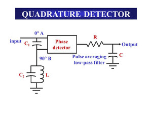
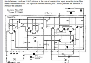
Quadrature Demodulation : FM検波。AM検波 TBA120.ULN2111 乗算回路
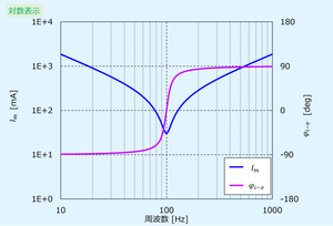
LCによる共振を利用する。相は揃う。
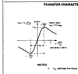
クワドラチャFM検波はスロープ検波の延長。
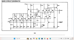
メーカーの説明では、3 stage balanced produt detector。
DATA sheet : uln2111を参照のこと
プロダクト検波なので、ssbの復調 あるいは同期検波に転用できるね。
****************************************
amの同期検波(負荷LCタイプ)
https://www.allaboutcircuits.com/textbook/radio-frequency-analysis-design/radio-frequency-demodulation/how-to-demodulate-an-am-waveform/
英語の説明。
These plots show the demodulated signal for three values of transmitter-to-receiver phase difference. As the phase difference increases, the amplitude of the demodulated signal decreases. The demodulation procedure has become nonfunctional at 90° phase difference; this represents the worst-case scenario—i.e., the amplitude begins to increase again as the phase difference moves away (in either direction) from 90°.
One way to remedy this situation is through additional circuitry that synchronizes the phase of the receiver’s reference signal with the phase of the received signal. However, quadrature demodulation can be used to overcome the absence of synchronization between transmitter and receiver. As was just pointed out, the worst-case phase discrepancy is ±90°. Thus, if we perform multiplication with two reference signals separated by 90° of phase, the output from one multiplier compensates for the decreasing amplitude of the output from the other multiplier. In this scenario the worst-case phase difference is 45°, and you can see in the above plot that a 45° phase difference does not result in a catastrophic reduction in the amplitude of the demodulated signal.
The following plots demonstrate this I/Q compensation. The traces are demodulated signals from the I and Q branches of a quadrature demodulator.
おおざっぱに云うと
1:LC負荷のAM検波(同期検波): クワドラチャ検波(乗算回路+相補正回路)。
受信電波とIF段の信号; 相が90度異なると出力は最小になる。 したがって処理信号が受信電波と相ゼロ度になるためのLC共振をつかっている。同相で乗算すれば音声信号だけでてくる。クワドラ検波ではDBMが使われいるので成立する。
同期検波のdet coil. lc並列共振の位相。±90度うごかせるのでどこかで同期する。
2:抵抗負荷での同期検波 : 純粋な乗算回路。
MC1496等DBMだけでの同期検波は、DBMは抵抗負荷の乗算回路として動作している。
LC負荷の乗算回路(クワドラチャ検波)として使う場合には、搬送波の入れ方は弱くすること。
。
**************************************************************
TBA120は等価回路が示すように同期検波にはなる。 バイアスは実験してきめる必要ある。
SSB.AMにはULN2111が楽そうなかんじ。
**********************************************


コメント